Robot Assembly
Step by Step photos of our robot's creation....
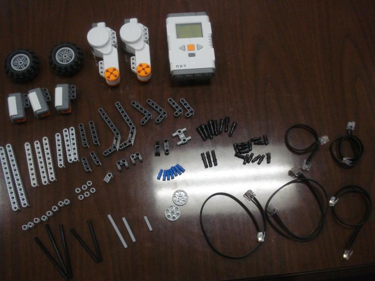 Step 0: All parts displayed |
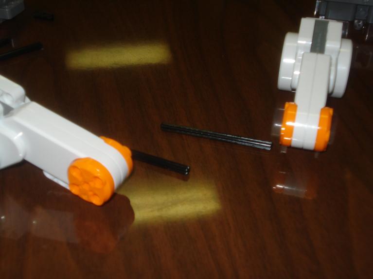 Step 1: 2 motors, 2 small black rods put into the motors |
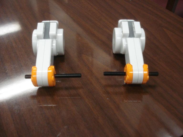 Display of motors with rods in them |
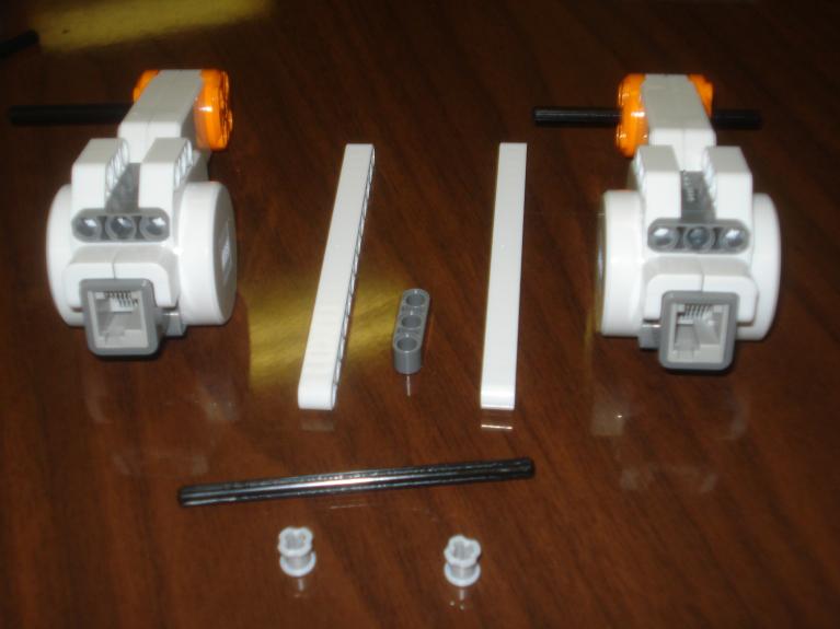 Step 2: 2 13-hole bars (HB), one 3-hole HB, all held together by long black rod, attaches the motors together...there are also full spacers to keep it in place |
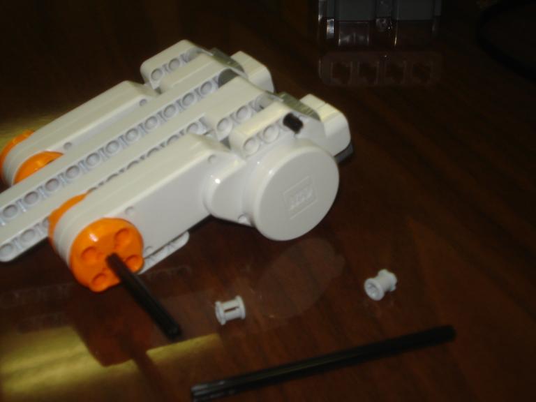 Step 3: Add another black rod and two full spacers too |
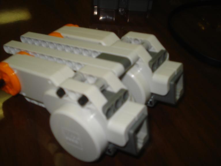 Display |
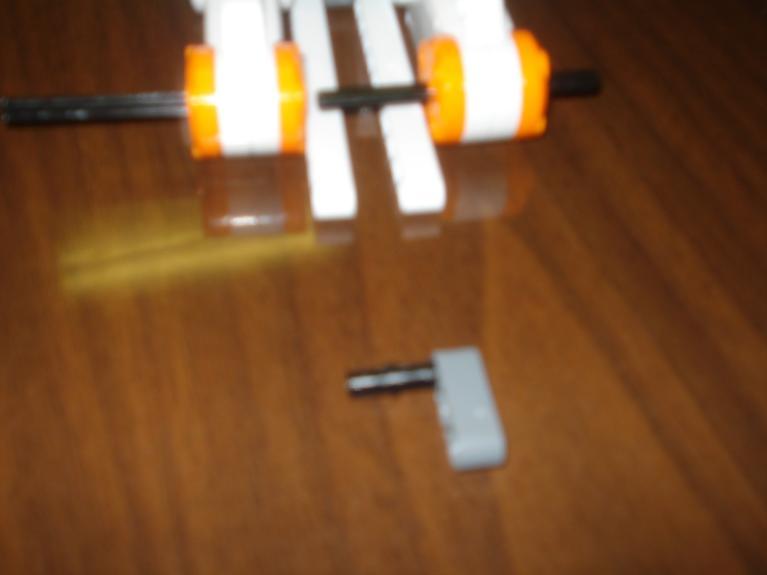 Step 4: Attach 3-hole HB to double connector and attach to the end of the 13-hole HBs |
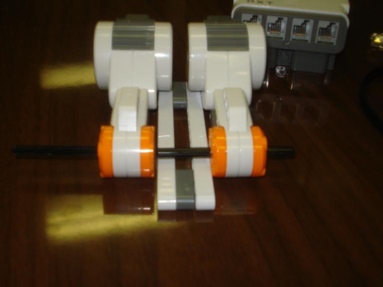 Display |
 Step 5: L bar with two connectors and then "binocular" looking gray thing with double connector which holds the light sensors in place |
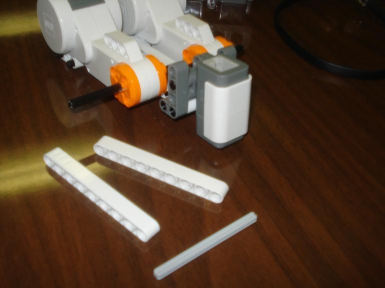 Step 6: 2 9-hole HBs and gray rod to center sensor |
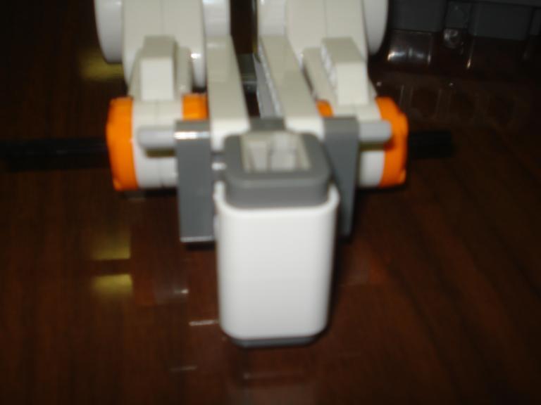 Display |
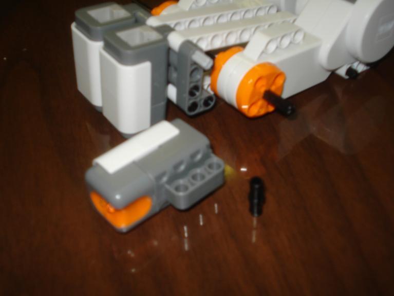 Step 7: Add 2 other sensors using connectors and L bars |
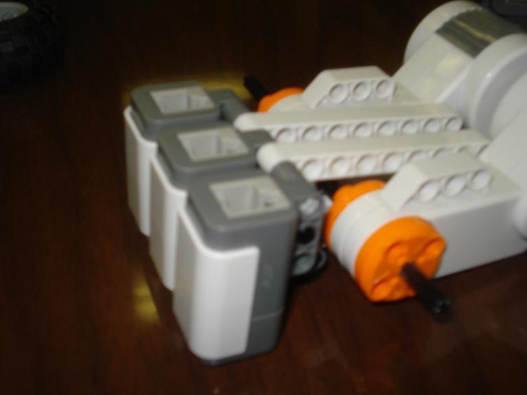 Display |
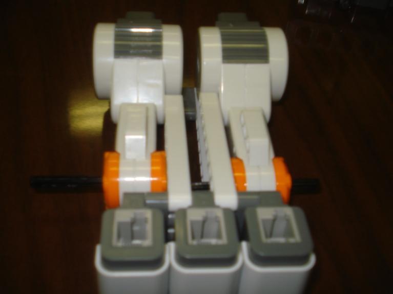 More Display |
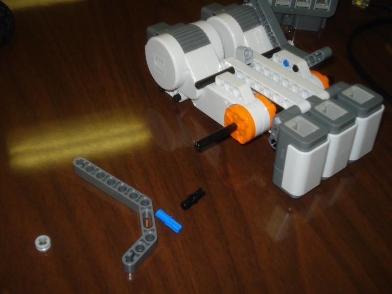 Step 8: Add J bar with connector and blue connector on each side of the motors and a black rod with a "bi-directional" bar for more stability |
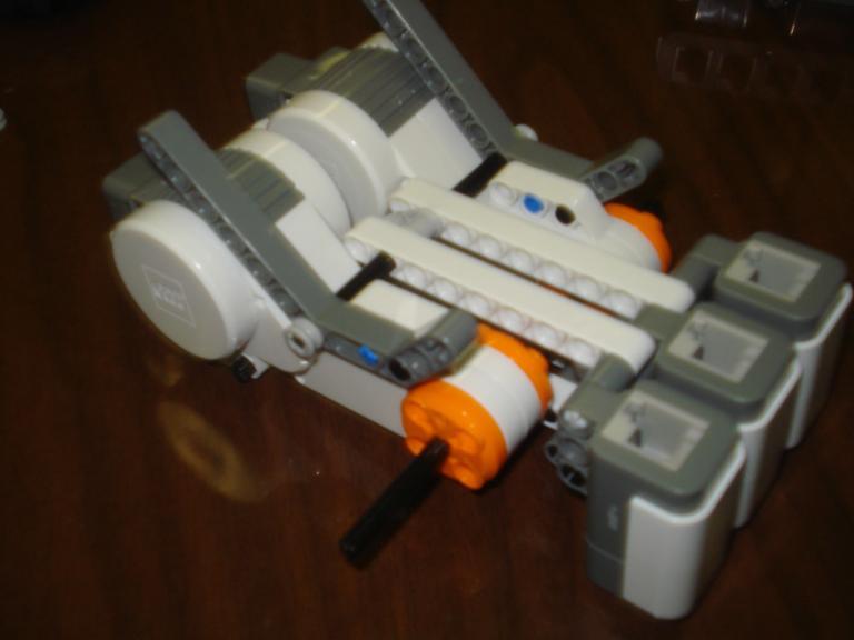 Step 9: Half spacers to keep the rod in place |
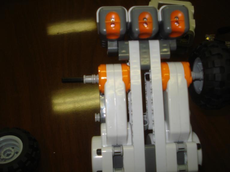 Step 10: Half spacer, then full spacer, then wheel, then full spacer on each axle |
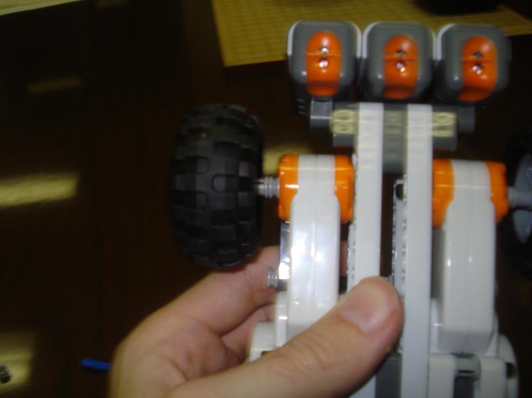 Display wheels |
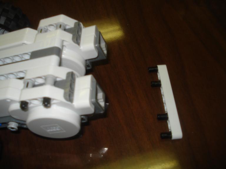 Step 11: A 9-hole HB with connectors in holes 1,3,7,9 to attach to the gray holes on the back of the motors |
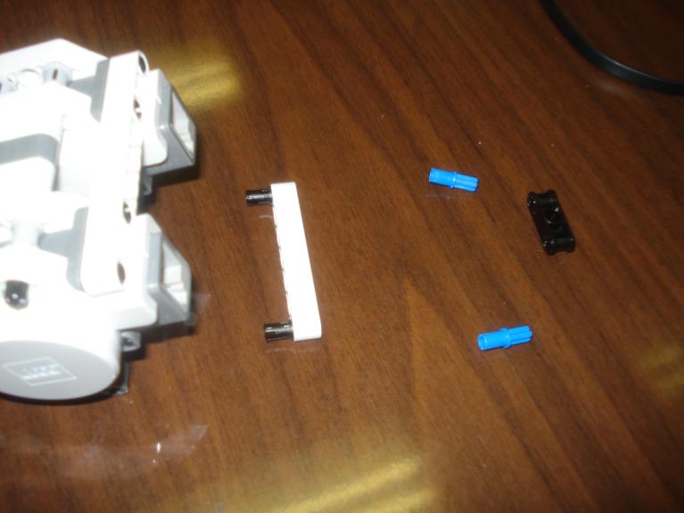 Step 12: A 7-hole HB with connectors in holes 1,7 to attach to the previous 9-hole HB in Step 11 in holes 2,8 Two blue connectors into "black thing" which goes into this step's HB in holes 3,5 |
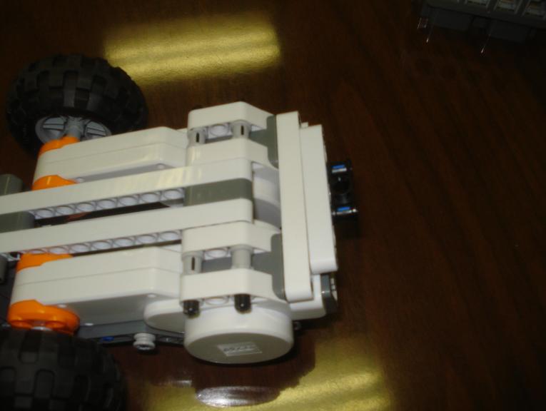 Display |
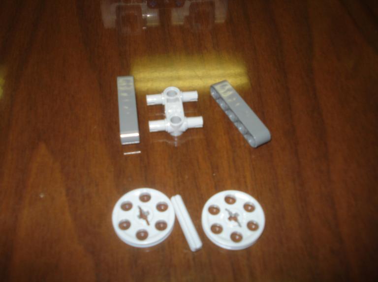 Step 13: 2 gray 5-hole HBs attached by an "I" connector with the half width small wheels (2) on a small gray rod |
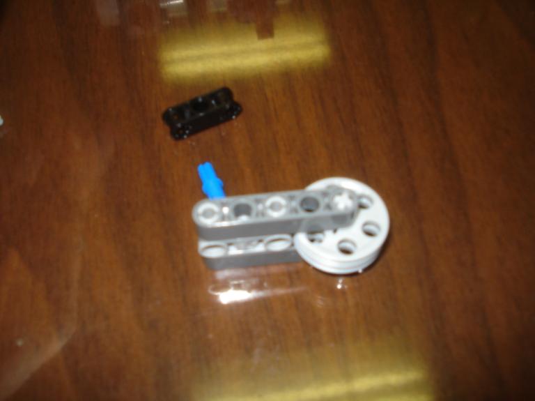 Step 14: Add a blue connector and another "black thing" to complete the wheel system |
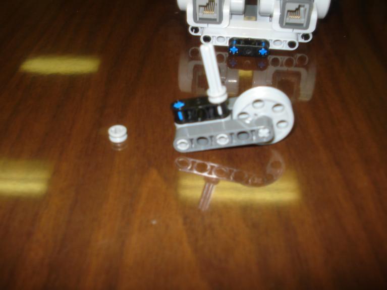 Step 15: Add a #5 gray rod to the wheel with a half spacer |
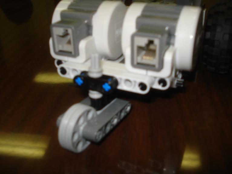 Step 16: Add wheel to the back of the robot with a half spacer holding it on |
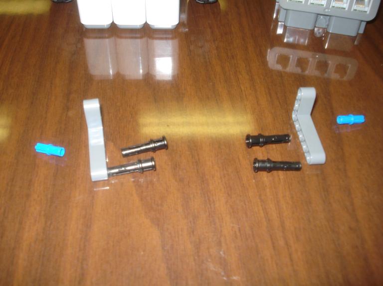 Step 17: 2 big L bars with 2 blue connectors and 4 "assisting" connectors |
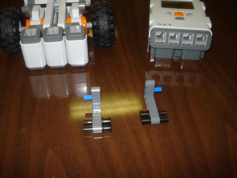 Display of how they go together |
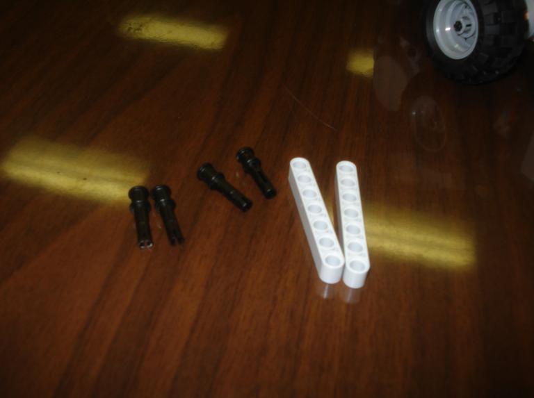 Step 18: 2 7-hole HBs and 4 "assisting" connectors which go into holes 1,7 |
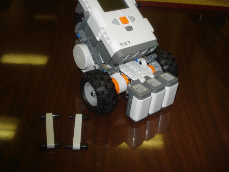 Step 19: Display of previous step as well as attachment of brick using L bars from Step 17 |
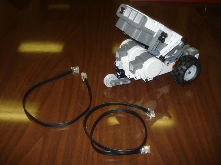 Step 20: Attach 7-hole HBs to brick, and displaying of wires Right motor into port B Left motor into port C |
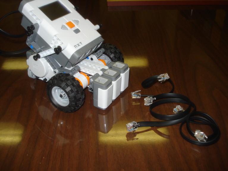 Step 21: 3 short wires for the light sensors Left sensor into port 4 Middle sensor into port 3 Right sensor into port 2 |
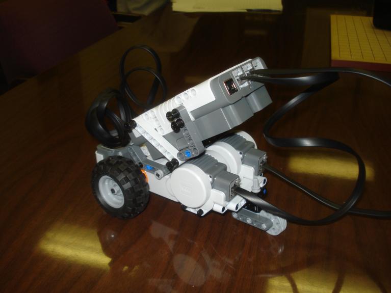 Display of back |
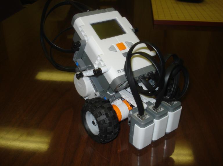 Display of front |