Honey Badger
An Arduino Robot Project
Part I. Hardware:
Hardware |
Description |
|---|---|
 |
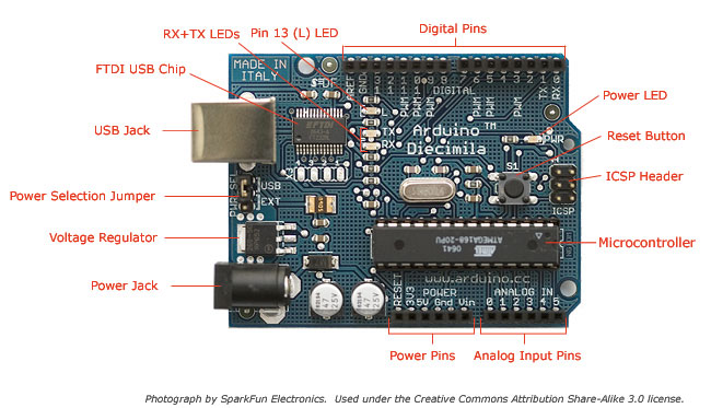
The Arduino Diecimila is a microcontroller board based on the ATmega168 (datasheet). It has 14 digital input/output pins (of which 6 can be used as PWM outputs), 6 analog inputs, a 16 MHz crystal oscillator, a USB connection, a power jack, an ICSP header, and a reset button. It contains everything needed to support the microcontroller; simply connect it to a computer with a USB cable or power it with a AC-to-DC adapter or battery to get started. |
 |
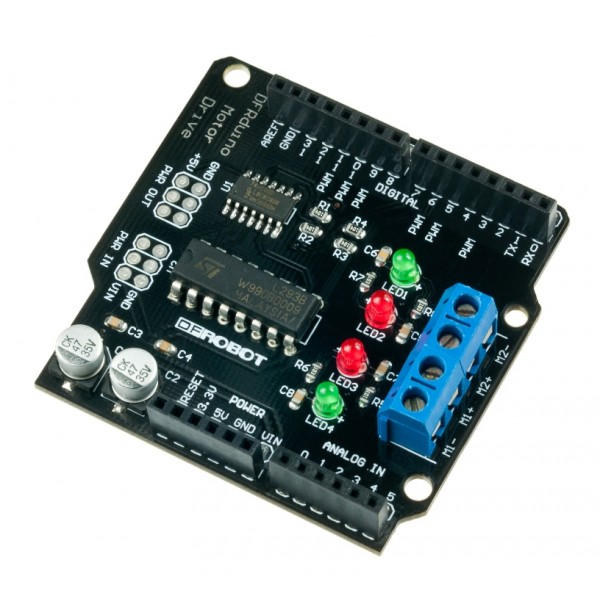
This motor shield allows Arduino to drive two channel DC motors. It uses a L293B chip which deliveries output current up to 1A (2A for L298P version) each channel. The speed control is achieved through conventional PWM which can be obtained from Arduino’s PWM output Pin 5 and 6. The enable/disable function of the motor control is signalled by Arduino Digital Pin 4 and 7. Roboduino Motor Shield uses PWM output Pin 6 and 9 and Digital Pin 7 and 8. The Motor shield is powered directly from Arduino. It is strongly advised that use external power supply (on Arduino) to power the Arduino instead of the USB power supply. |
 |
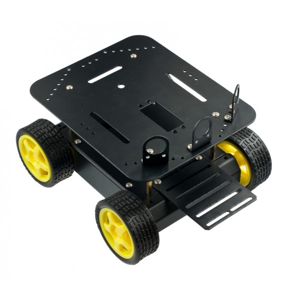
The DFRobot 4WD Arduino Mobile Platform is intended for use with the DFRobot ROMEO Microcontroller and includes 4x drive motors, 4x wheels and a complete chassis with mounting hardware. The included second level allows you to add even more electronics and even has a space for a standard servo motor. The high-strength aluminum alloy body material provides flexibility in rapid movement particularly in outdoor grass, gravel, sand or sloped surface. The 4WD Arduino Mobile Platform is also suitable for robot competitions and research related projects. The platform was modified to use only 2 wheels and caster wheel. |
 |
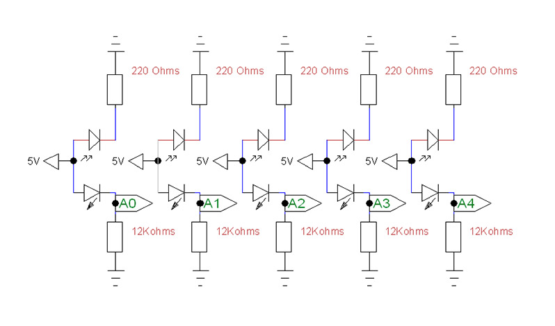
Custom made sensors made of photoresistors and red LED's. The picture illustrates the latest design. Original design used only 3 LED's. |
Part II. Modifications/Diagram:
The sensor diagram (A0-A4 are the analog inputs on arduino board):


Part III. Design description:
Our design is very simple; the board is mounted at the top of the robot. At the front are five LED/light sensor pairs, just ahead of the wheels. The sensors are, very whimsically, separated from the LED's by a cut-off piece of a tea packet. The sensors are not evenly spaced; there is one at either side and three clustered near the center. At the back of the robot is a single slider. This design has changed twice during the course of the semester. The first of these was following the first in-class presentation. The wheels were initially at the opposite end of the robot, which despite suiting the factory specifications of the robot's body, made turning occasionally unwieldy. The wheels were moved to their current position nearer to the sensors. Aside from that modification, the design remained largely unchanged until very late in the project, when more sensors were added to correct for programmatic difficulty in traversing intersections using only three.
Part IV. TO DO:
Throughout the project we have changed batteries multiple times. Taking under consideration that these batteries were single use only, there would be a huge advantage of using rechargeable battery pack. Another, huge need is to invest in sensor modules that can be easily attached/adjusted as opposed to re-soldering individual elements on prototyping PCB board that as matter of fact is not good for multiple re-soldering attempts. This would allow easy testing of different scenarios as well as would save time (re-soldering a PCB board with 5 sensors takes few hours and you really would not have any desire to spend another few hours to solder everything back if you want to retract your design change).